
What Is a Motor Coil Winding Machine and How Does It Work?

A motor coil winding machine is the equipment that forms and places insulated copper wire inside an electric motor’s stator or rotor. It controls wire tension, winding speed, turn count, and coil position. This process may look simple. It is not.

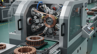
Dr. Ion Boldea, a respected motor-design authority, has observed, “A motor’s electromagnetic performance depends strongly on the quality of its windings.” That principle explains why manufacturers use a motor coil winding machine instead of relying only on manual work. The machine guides fine copper wire around a precise former or directly into stator slots. Its nozzle moves in measured paths while sensors monitor tension and alignment. A small error can create loose turns, damaged insulation, or uneven magnetic performance.

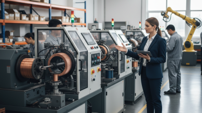
In a typical production line, an operator loads the stator, selects a winding program, and checks the first completed coil. The machine then repeats the pattern consistently. Fast, but not careless. Modern systems may include automatic wire cutting, coil insertion, tension correction, and digital quality records. These features improve repeatability, although they cannot replace skilled inspection.

Real production is rarely perfect. Wire diameter may vary slightly. Insulation can weaken during sharp bends. Even a well-calibrated machine needs periodic adjustment and cleaning. Understanding how a motor coil winding machine works therefore requires more than studying its motors and software. It requires observing the wire, the tooling, and the finished coil closely. That practical view reveals both the machine’s strengths and its limits.
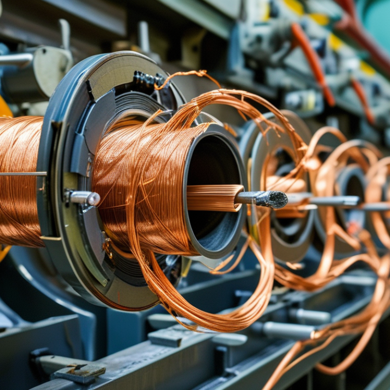
What Is a Motor Coil Winding Machine and How Does It Work?

What Is a Motor Coil Winding Machine?

A motor coil winding machine is equipment designed to place insulated copper wire around a stator, rotor, or coil form. It creates the electromagnetic coils used inside electric motors. Depending on the model, it may operate automatically, semi-automatically, or with direct operator control.

The machine usually combines a rotating spindle, wire guides, tension controls, and programmable settings. The spindle turns the core while the guide moves the wire across its surface. This movement controls the number of turns, winding direction, spacing, and layer position.

A typical cycle may include loading the core, setting the wire tension, winding the programmed turns, and securing the finished lead. Small details matter.

In practical workshops, technicians check the wire path before production begins. They also inspect insulation, measure resistance, and compare the actual turns with the programmed value. A machine improves consistency, but it cannot fix poor material or incorrect settings.

Excessive tension may stretch the wire. Loose tension may create uneven layers. The process is not completely foolproof.

Operators sometimes need to adjust speed or guide alignment after examining the first coil. This hands-on review can prevent defects that software alone may miss.

Key Components and Their Functions

What Is a Motor Coil Winding Machine and How Does It Work?

A motor coil winding machine forms insulated copper wire into precise coils for stators or rotors. Its key components include the wire-feeding system, tension controller, winding spindle, guide nozzle, indexing table, and programmable control unit. The feeder supplies wire smoothly, while the tension controller prevents loose turns or insulation damage. The spindle rotates the coil former at a controlled speed. The guide nozzle places each turn in a defined position. The indexing table then moves the workpiece between slots or winding stations.

The controller coordinates speed, turns, pitch, and stopping positions. Sensors monitor wire tension, spindle movement, and possible breaks. This matters because the International Energy Agency reports that electric motors consume roughly half of global electricity. Small winding errors can therefore reduce efficiency across millions of machines. The U.S. Department of Energy also identifies motor systems as major industrial energy users. In factory trials, stable tension often improves coil consistency more than simply increasing speed. That detail is easy to underestimate. A faster machine can create more rejects.

Tips: Check wire tension before raising speed. Inspect the guide nozzle for wear. Record turn counts and stopping positions. Operators should compare the first coil with the production drawing, not memory. No machine is perfectly self-correcting. Temperature, wire diameter, and insulation friction can still change the result. Regular calibration remains necessary, even when the winding pattern looks correct.

How the Coil Winding Process Works Step by Step

A motor coil winding machine forms insulated copper wire into precise coils for a motor’s stator or rotor. Its work matters because motor-driven systems consume about 53% of global electricity, according to the International Energy Agency’s Energy Efficiency 2019 report. Small winding errors can increase heat, noise, and energy loss.

The process starts with setup. An operator enters wire diameter, coil turns, pitch, and winding speed into the control system. The machine then guides wire from a tension-controlled spool through ceramic or polymer guides. A rotating spindle positions the former, while a traverse mechanism places each turn beside the last one. The wire must remain tight, but not stretched. Too much tension can damage insulation.

The machine counts turns electronically. It also controls spindle speed and stopping position. After each coil, the operator checks its shape, lead length, and insulation condition. A continuity test can reveal broken conductors, while resistance testing identifies uneven connections. The U.S. Department of Energy reports that motor systems represent roughly 69% of industrial electricity use, making efficient production important. Yet automation does not remove every risk. Dust, worn guides, or incorrect tension settings can still create defects. I have found that visual inspection remains valuable, especially when the coil looks acceptable but feels uneven. The final coil is inserted, connected, and tested before assembly continues.

What Is a Motor Coil Winding Machine and How Does It Work?

Step Process Stage What the Machine Does Key Control Variables Typical Result or Quality Check
1 Motor Design Review Loads the winding program based on the stator or coil-form design. Slot count, pole configuration, coil pitch, wire diameter, number of turns. A verified winding recipe that matches the electrical drawing and tooling.
2 Wire Preparation Feeds enamel-coated copper or aluminum wire from a supply spool through guides and tension-control components. Wire size, insulation type, feed direction, tension, spool alignment. Smooth wire travel without scratches, kinks, excessive tension, or insulation damage.
3 Tool or Stator Positioning Positions the coil former, needle, flyer, or stator so the wire follows the programmed path. Fixture alignment, insertion depth, angular position, tooling clearance. The winding area is centered and all moving parts have sufficient clearance.
4 Lead-Wire Placement Creates and routes the starting lead before the active winding begins. Lead length, routing position, clamping force, terminal location. The lead is long enough for termination and remains securely positioned.
5 Coil Winding Rotates the former or stator while guiding the wire into successive turns and layers. Spindle speed, traverse speed, wire tension, turn count, winding direction. Uniform turns with controlled packing, correct coil geometry, and the programmed turn count.
6 Layer Management Controls the wire path to form orderly layers and prevent overlaps outside the winding window. Traverse pitch, layer sequence, edge position, dwell time, tension stability. Consistent coil height and width with minimal gaps, crossovers, or bulges.
7 End Lead Formation Stops at the programmed turn count and routes the finishing lead to its required terminal or connection point. End-lead length, exit angle, cut position, clamping sequence. A clearly defined end lead that is ready for connection, soldering, or termination.
8 Wire Cutting or Clamping Cuts, clamps, or temporarily holds the wire while preserving the coil shape. Cutting timing, clamp pressure, residual lead length, blade condition. A clean wire end without crushing, nicking, or loosening the completed coil.
9 Coil Transfer or Indexing Moves the finished coil to the next position or indexes the stator for the following coil group. Index angle, transfer timing, fixture position, insertion force. Correct coil placement and phase sequence without damaging adjacent windings.
10 Electrical and Visual Inspection Checks the winding against mechanical and electrical requirements before final assembly. Resistance, continuity, insulation resistance, turn count, coil dimensions. A winding that meets design specifications and is free from visible insulation or placement defects.
Main Machine Functions and Their Purpose
Machine Function Purpose Why It Matters
Wire Tension Control Maintains a stable pulling force on the wire. Excessive tension can stretch or damage insulation, while low tension can create loose and irregular turns.
Rotary Drive Rotates the former, flyer, or stator during winding. Accurate rotation determines winding speed, direction, and turn placement.
Traverse or Guide System Moves the wire laterally across the coil width. Controls coil pitch, layer formation, and the overall winding profile.
Programmable Controller Coordinates speed, position, turn count, indexing, and machine sequences. Repeatable digital control improves consistency between coils and production batches.
Fixture and Tooling Holds the stator, rotor component, bobbin, or coil former in position. Proper support prevents movement and helps maintain dimensional accuracy.
Safety and Fault Monitoring Detects wire breaks, overloads, open guards, position errors, and abnormal operating conditions. Protects operators, tooling, and workpieces while reducing defective windings.

Machine Types and Winding Methods

A motor coil winding machine forms insulated copper wire into controlled coils for electric motors. It coordinates spindle speed, wire tension, guide movement, and stopping position. During operation, a fixture rotates while a guide places each turn beside the previous turn. Good tension prevents loose loops and damaged enamel. In practice, operators check the initial coil manually because one incorrect pitch can affect resistance and balance.

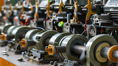
Machine types vary with motor geometry and production volume. Flyer winding machines suit many stator coils and offer flexible wire placement. Needle winding machines guide wire through narrow slots, making them useful for compact stators. Spindle or armature winders rotate the workpiece while shaping coils around a core. Toroidal winders follow a different path and pass wire through the core repeatedly. Automatic models add programmable recipes, tension control, and wire-cutting functions. Semi-automatic equipment still depends heavily on operator alignment and inspection.

Common winding methods include random winding, precision winding, and layered winding. Random winding fills space quickly, but wire crossing can reduce packing consistency. Precision winding places turns in a defined pattern, improving repeatability and heat transfer. Layered winding builds neat rows for coils requiring predictable dimensions. Engineers should match the method to slot shape, wire diameter, insulation class, and fill factor. One limitation remains: settings that work on one wire size may fail on another. Trial coils, resistance tests, and visual checks expose these gaps before full production.

Motor Coil Winding: Synchronous Speed by Pole Count

A motor coil winding machine places insulated wire into stator slots according to the selected winding design. The chart shows the theoretical synchronous speed of a rotating magnetic field at 50 Hz for common pole counts. Actual motor speed is slightly lower because of slip in induction motors.

Common machine configurations include coil-winding machines for preformed coils, needle-winding machines for concentrated windings, flyer-winding machines for distributed windings, and toroidal winders for ring-shaped cores. The synchronous-speed relationship used here is n = 120 × f ÷ P, where n is speed in revolutions per minute, f is frequency in hertz, and P is the number of poles.

Quality Control, Applications, and Maintenance Needs

A motor coil winding machine places insulated copper wire into precise coils for electric motors. It controls tension, speed, turns, and wire positioning during production. The spindle rotates while a guided nozzle follows a programmed winding path. Small errors can create loose layers, damaged insulation, or uneven coil resistance.

Quality control starts with incoming wire inspection and insulation checks. Operators should verify wire diameter, tension settings, turn counts, and coil dimensions. A resistance test can reveal missing turns or poor connections. Surge testing may identify weak insulation before assembly. Visual inspection still matters. Tiny scratches are easy to miss. In my experience, a clean winding pattern often signals stable machine control, but it does not prove electrical reliability. Temperature, vibration, and operator handling can change results. Records should include batch numbers, test values, and rejected coils.

These machines support motors used in pumps, fans, appliances, industrial equipment, and electric vehicles. Each application may require different wire sizes, coil shapes, and production speeds. Maintenance should include daily cleaning around the guide, nozzle, and tension unit. Lubricate moving parts according to the equipment manual. Inspect belts, bearings, sensors, and clamps for wear. Recalibrate tension and positioning after repairs. Do not ignore unusual noise. A short stop is cheaper than a damaged stator. The process is efficient, but not flawless. Overconfidence remains a practical maintenance risk.